|
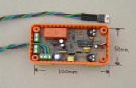
Home brew electronic speed controller.
Most speed controllers these days use an IC to control the
speed of the Motor. The chips they use
are Pics....Programmable Integrated Circuit. The way they work is rather
the like the Bobs Boards, it increases or decreases the speed in steps.
but unlike the Bobs Boards the use very little current.
(Bob Boards are a variable resistor mechanical speed controller.)
The result is a motor that speeds up or down in small steps & can be quite
jerky.
Before the advent of the Pic there was an IC which was dedicated to this
job. This chip is called a server motor controller & this is
what all the makers of speed controllers used. This chip is very good as
the speed control is very smooth & responsive.
After a time they stopped making this chip & is now obsolete. So that's
why they now use Pics.
I found this out just after they stopped making the chip & managed to get
hold of some. Had to buy a all a dealers stock.....3000 of them!! But
managed to sell on most of them except for a few
for myself.
So armed with the chips & some expert help from a fellow radio
amateur, we came up with a suitable circuit for the controllers that I now
use. After that it was just a case of making the printed circuit boards,
getting the soldering iron out + a shoe horn to get it all in the smallest
box I could find!!
They can handle 6 - 24 Volt & up to
around 25 amps. The first one used to cut out after a while running on 6
Volts but after a while it worked again for a while. It was found that the
FET (Field Effect Transistor) was folding over & shutting down at 150 deg
C!! So much so that the top of the plastic box was deformed!!!.....Now
sorted by the use of a metal plate glued to the hull under the water line
& the FET screwed to the plate...Thus water cooled FET.
 |